

Introduction
Fiber laser marking machines have become essential tools in modern manufacturing, offering permanent, high-contrast marks on metals, plastics, and ceramics at speeds that traditional engraving methods cannot match. Whether you are adding serial numbers to aerospace components, branding logos on consumer electronics, or creating traceability codes on automotive parts, knowing how to operate a fiber laser marking machine correctly is the difference between consistent quality and costly scrap. This guide walks you through every step — from unpacking the machine to running production jobs — so you can achieve professional results with confidence.
What Is a Fiber Laser Marking Machine?
A fiber laser marking machine uses a solid-state laser source with a doped optical fiber as the gain medium, producing a 1064 nm infrared beam that is highly absorbed by metals and many plastics. Unlike CO₂ or Nd:YAG lasers, the entire laser cavity is enclosed within the fiber itself — no gas tubes to refill, no flash lamps to replace, no free-space optics to realign. This monolithic construction gives fiber laser sources a service life of 50,000 to 100,000 operating hours before major maintenance is needed, making them a long-term investment for production environments. Most laser marking machine units are Class 4 laser devices and can cause eye and skin injury from direct or reflected beam exposure, so following proper safety protocols — which we cover in the next step — is not optional.
Step 1: Safety Preparation — Before You Power On
Every operator should treat the laser marking machine with the same respect as any heavy industrial machine. The ANSI Z136.1 standard, recognized by OSHA as the industry benchmark for laser safety, requires a written Standard Operating Procedure (SOP) for Class 4 lasers. For any industrial laser marking setup, before your first job, arrange these safety essentials:
- Laser safety eyewear rated for 1064 nm with an optical density (OD) of 5+ — this is non-negotiable even if the machine has an enclosure.
- Interlocked enclosure or laser-controlled area with warning signs posted both inside and outside the entryway.
- Fume extraction system — marking metals and plastics generates airborne particulates that must be captured at the source to keep the breathing zone safe.
- Fire extinguisher rated for electrical fires within reach of the workstation.
Designate a Laser Safety Officer (LSO) for your facility. This person is responsible for enforcing the SOP, maintaining training records, and conducting periodic safety audits. A well-prepared safety environment is the foundation of every successful fiber laser marking operation.
Step 2: Unpacking, Positioning, and Hardware Connections
Position the laser marking machine on a stable, level workbench or integrate it into an existing production line. Most fiber laser marking machines are air-cooled and run on standard single-phase 220V power, drawing around 200W total — far less than a CO₂ laser of comparable output. The compact footprint means a typical desktop fiber laser marker fits comfortably on a standard workbench without dedicated floor space.
Complete these connections in order:
- Power cable — verify the voltage matches your local supply before plugging in. A voltage stabilizer is recommended in regions with unstable mains power.
- USB or Ethernet cable between the laser controller and your computer for software communication. Use a dedicated USB 2.0 port if possible — some controllers are incompatible with USB 3.0.
- Emergency stop button — confirm it is accessible and interrupts power to the laser source immediately when pressed.
- Foot switch or trigger signal (if used in production mode) — connect to the I/O port on the controller for hands-free operation.
- Fume extraction hose — attach to the exhaust port on the back panel and route to your extraction system. A minimum airflow of 200 m³/h is recommended for most desktop units.
Step 3: Software Installation and Driver Setup
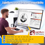
Most fiber laser marking machines use EzCad2 or EzCad3 as the primary control software, though some newer models support LightBurn for users who prefer a more intuitive interface. Install the software from the USB drive provided with the laser marking machine, then connect the USB driver. On Windows, the system should recognize the laser controller as a COM port device.
Open the software and verify communication: the status bar should show “Laser connected” or display the controller model. If the connection fails, try these steps:
- Reinstall the USB driver from the manufacturer’s installation package.
- Try a different USB port — avoid USB hubs or front-panel ports.
- Check the Device Manager for any unrecognized devices under “Ports (COM & LPT)”.
- Restart the controller by cycling the power switch.
Once the software confirms communication, set the marking field size to match your lens (e.g., 110×110 mm for a standard F-theta lens). Incorrect field settings cause the mark to appear distorted or scaled wrong.
Step 4: Setting the Correct Focal Height
The focal length of the lens determines the distance from the laser head to the workpiece surface. For a standard F-theta lens (commonly 160 mm, 200 mm, or 254 mm), the marking field size and focal distance are fixed. Most manufacturers supply a focusing ruler or gauge block that matches the exact focal length of the installed lens.
To set the focus on your fiber laser marking machine:
- Place the workpiece on the marking platform.
- Lower the laser head until the focusing tool touches the workpiece surface.
- Lock the Z-axis in position using the thumbscrew or locking collar.
- Remove the focusing tool and use the red light preview to verify the marking area covers the intended position.
A correct focus is critical — even a 1 mm deviation can blur the mark, reduce contrast, or cause inconsistent depth across the field. If your parts vary in thickness, consider using an auto-focus or dynamic focus module to maintain consistent focal distance without manual adjustment.
Step 5: Understanding the Key Marking Parameters
Five parameters control every mark a fiber laser marking machine produces. Getting them right for your material is the core skill of operating any laser marking machine.
| Parameter | What It Controls | Typical Range | Effect When Increased |
|---|---|---|---|
| Power | Percentage of maximum laser output | 10–100% | Deeper, darker mark; risk of burn-through on thin materials |
| Speed | Galvanometer scan speed across the workpiece | 500–10000 mm/s | Shallower mark; shorter cycle time |
| Frequency | Number of laser pulses per second (kHz) | 20–200 kHz | Lower freq = higher peak power, better for deep engraving; higher freq = smoother surface for plastics |
| Hatch / Line Spacing | Distance between adjacent scan lines | 0.01–0.10 mm | Tighter spacing = denser fill, smoother look; wider spacing = faster, rougher finish |
| Loop Count | Number of passes over the same area | 1–50+ | Greater depth; increased processing time |
Starting Parameter Recommendations by Material
Use these baseline settings as a starting point for your fiber laser, then adjust based on the visual result:
- Stainless steel (black annealing mark): Power 70–80%, Speed 2000–3000 mm/s, Frequency 60–80 kHz, Hatch 0.02 mm, 1 loop. This produces a dark oxide layer without removing material.
- Aluminum (deep engraving): Power 100%, Speed 1500 mm/s, Frequency 30–40 kHz, Hatch 0.03 mm, 5–10 loops with 90° cross-hatch for uniform depth.
- Plastic (ABS, polycarbonate): Power 15–25%, Speed 3000–5000 mm/s, Frequency 80–100 kHz, Hatch 0.04 mm, 1–2 loops. Keep power low to avoid melting or carbonization.
- Brass and copper: Power 60–80%, Speed 2000–3000 mm/s, Frequency 50–70 kHz, Hatch 0.02 mm, 1–3 loops. Copper’s high reflectivity may require multiple passes.
Each material responds differently, so running a test matrix on a sample piece before production is always recommended. This is a standard practice in industrial laser marking to ensure consistent quality.
Step 6: Creating Your Design and Configuring the Job
In the marking software, import or create your design — text, logo, serial number, barcode, or Data Matrix code. Most EzCad-based software packages that ship with fiber laser marking machines support vector files (DXF, PLT, AI) and bitmap images (BMP, JPG, PNG). Key settings to configure before marking:
- Marking field size — match the dimensions of your lens. A 160 mm lens typically covers 110×110 mm; a 254 mm lens covers 200×200 mm.
- Pen parameters — assign power, speed, frequency, and loop count to each “pen” (color group) in the design. Different colors in the drawing can have different parameters in the same job.
- Red light preview — use this to visualize the mark position on the workpiece before firing the fiber laser. Adjust the X-Y offset if the red dot does not align with the laser output.
- Array marking — set the number of copies and row/column spacing if marking multiple parts in one cycle to maximize throughput.
Step 7: Running a Test Mark on Scrap Material
Never start a production run without a test. Use a piece of the same material you intend to mark, ideally from the same batch — surface finish, coating, and alloy composition all affect mark quality. Even two batches of the same stainless steel grade can produce different contrast levels.
Run a parameter matrix test: divide the test piece into a grid of 6–8 cells and vary one parameter (e.g., power from 30% to 100% in 10% steps) while keeping the others constant. This reveals the optimal setting for your laser machine with minimal waste. Evaluate the test mark for:
- Contrast — is the mark clearly readable against the background? A good industrial laser marking result should be legible under normal workshop lighting.
- Edge sharpness — are the edges clean or are there burn marks, recast, or halo effects?
- Depth — for deep engraving, measure with a depth gauge after each set of passes. Reaching 0.2–0.4 mm may take 8–20 passes depending on the alloy.
- Repeatability — mark the same test pattern twice and compare the results. If the two marks differ, check the focal height and material fixturing.
Step 8: Production Marking and Quality Control
Once the test mark passes your quality criteria, you are ready for production. The following practices help maintain consistency across hundreds or thousands of parts:
- Fixture each part in the same position — even 0.5 mm of position drift shifts the mark location. Use custom jigs or vacuum fixtures for repeatable positioning.
- Log your parameters for each job so you can reproduce the result weeks or months later. A simple spreadsheet with material, power, speed, frequency, hatch, and loop count is enough.
- Inspect the first piece of every batch, then spot-check at regular intervals (e.g., every 50th part). Use a vision inspection system if available for automated verification.
- Monitor the laser source temperature — if the chiller or air-cooling fan fails, the laser diode lifetime drops sharply. Most controllers display a temperature reading; stop the machine if it exceeds 35°C.
According to the RP Photonics Encyclopedia, a vendor-neutral reference on laser technology, high-power fiber laser systems can achieve wall-plug efficiencies of around 50%, meaning roughly half the electrical power drawn from the wall is converted into useful laser light. This efficiency keeps operating costs low even during high-throughput production runs.
Daily Maintenance Tips for Long Service Life
Fiber laser marking machines require significantly less maintenance than CO₂ or YAG lasers, but they still need regular care to reach their full service life:
- Clean the protective window (the glass between the lens and the workpiece) daily with a lens-grade cleaning solution — smoke residue from marking absorbs beam energy and causes local heating that can crack the window.
- Check the air intake filter weekly — a clogged filter reduces cooling efficiency and can trigger thermal shutdown during long runs.
- Inspect fiber optic cables monthly — do not bend them to a radius smaller than 10 cm, as sharp bends damage the fiber core and reduce output power permanently.
- Keep the galvo mirrors clean — dust on the scan mirrors scatters the beam, reducing delivered power at the workpiece. Use compressed air or a soft optical brush.
- Update the control software when new versions are released to access bug fixes and parameter improvements.
With proper care, the pump diodes in a fiber laser source typically last 80,000 to 100,000 hours — equivalent to 9–11 years of continuous single-shift operation. This longevity is a major reason why fiber laser marking machines have replaced older technologies in most industrial laser marking applications.
Common Applications of Fiber Laser Marking
Industrial laser marking with fiber laser sources is used across virtually every manufacturing sector. The wavelength and beam quality of a fiber laser marking machine make it suitable for permanent marking on a wide range of materials:
- Automotive: VIN plates, engine components, brake calipers, transmission parts, and battery terminals marked for lifetime traceability. Marks must survive oil, heat, and mechanical abrasion.
- Aerospace: Turbine blades, landing gear components, and fasteners with serial numbers that must remain legible through extreme temperature cycles and chemical exposure.
- Electronics: PCB boards, connectors, switches, capacitors, and semiconductor packages marked with date codes, logos, and 2D Data Matrix codes at line widths down to 0.01 mm.
- Medical devices: Surgical instruments and implants marked with UDI (Unique Device Identification) codes per FDA requirements. The non-contact nature of laser marking machine operation eliminates contamination risks.
- Jewelry and luxury goods: Rings, watches, and pens engraved with logos, serial numbers, or decorative patterns. MOPA fiber laser systems can produce color marks on stainless steel and titanium for aesthetic branding.
Application requirements vary widely by industry and material. For a closer look at how these use cases compare in practice — including marking quality criteria, sample testing, and the questions to confirm before you buy — see this comprehensive fiber laser marking application review guide.
Conclusion
Operating a fiber laser marking machine is a learnable skill that delivers significant value once mastered. The key steps are: set up a safe workspace following ANSI Z136.1 guidelines, install the hardware and software correctly, dial in the focal height and parameters for your specific material, test on scrap, then run production with consistent quality checks. The low maintenance requirements and long service life of fiber laser sources make them one of the most cost-effective solutions for industrial laser marking today.
For teams looking to add a fiber laser marking machine to their production line, explore the range of fiber laser marking machines available at ActionLasers — from 20W optical fiber markers for fine electronics marking to 300W MOPA systems for high-speed industrial laser marking. Request a free sample processing test to verify the marking quality on your own parts before making a decision.